The 10k potentiometer is a core component in electronics, used to control voltage, current, and signal levels with simple physical movement. This guide covers everything you need to know—from understanding its pinout and working principle to wiring methods and real-world applications. Whether you're building a dimmer, tuning a sensor, or sending analog input to a microcontroller, this article gives you the clarity and confidence to use a 10k potentiometer effectively in your projects.
What Is a 10k Potentiometer and How Does It Work?
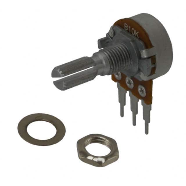
A 10k potentiometer is a basic three-terminal variable resistor designed to adjust resistance from 0 ohms up to 10,000 ohms. Commonly referred to simply as a potentiometer, it plays the role of a manual adjustment component used to control voltage levels, modify signals, and fine-tune circuit behavior. As a passive device, it requires no external power or supporting circuitry to function.
Key Features of a 10k Potentiometer
- Adjustable Resistance: Its main function is to precisely vary the electrical resistance in a circuit, enabling fine control of current or voltage.
- Three-Terminal Design: It consists of two fixed terminals at either end of a resistive path, and a third movable terminal known as the wiper.
- Dual Operating Modes: Thanks to its structure, a potentiometer can act both as a variable resistor and as a voltage divider.
- Compact and Reliable: It is commonly built to be small, robust, and durable, suitable for long-term use in electronic devices.
- Cost-Effective: With strong functionality and versatility at a low cost, the 10k potentiometer is widely adopted in various electronic applications.
How a 10k Potentiometer Works

At the heart of the potentiometer is a resistive element—a conductive strip between the two outer terminals. This strip has a fixed total resistance of 10k ohms. The center terminal connects to a wiper that physically moves along the resistive track. As the wiper moves, it changes the contact point on the track, splitting the total resistance into two variable portions.
- The resistance between the first terminal and the wiper is R1
- The resistance between the wiper and the third terminal is R2
- R1 and R2 always sum to the total resistance of 10k ohms
For example, if the wiper is positioned one-quarter along the track, R1 would be 2.5k ohms and R2 would be 7.5k ohms. Shifting the wiper changes these two values in opposite directions while maintaining a constant total. This complementary resistance relationship enables the potentiometer to smoothly regulate output voltage or limit current, depending on the connection.
also read: How Does a Photoresistor Work?
Material and Design Factors That Affect Potentiometer Performance
The performance of a 10k potentiometer depends on:
- The quality and stability of the resistive material
- The smoothness and conductivity of the wiper contact
- The mechanical build precision of the moving parts
Reliable performance across many adjustment cycles requires well-engineered materials and protection against wear, oxidation, and environmental effects.
10k Potentiometer Pinout Diagram

Understanding the Standard 3-Pin Layout of a Potentiometer
All potentiometers, regardless of their physical shape or size, share a consistent three-terminal electrical configuration. While the position or labeling of the pins may vary between manufacturers or models, the functional roles of each terminal remain the same.
Pin 1 (Fixed Terminal A / Input Voltage / Counterclockwise End)
This terminal is connected to one end of the internal resistive track. In most voltage divider setups, it is typically connected to the positive supply voltage. In rotary potentiometers, this may also be labeled as the counterclockwise end.
Pin 2 (Wiper / Output / Adjustable Terminal)
This is the center, movable terminal that connects directly to the internal wiper. When configured as a voltage divider, it delivers a variable output voltage. When used as a variable resistor, this pin provides the adjustable resistance connection point.
Pin 3 (Fixed Terminal B / Ground / Clockwise End)
This terminal connects to the other end of the resistive track. It is usually tied to ground in a voltage divider circuit and may be labeled as the clockwise end in some components.
How to Identify the Wiper and Fixed Terminals Without a Datasheet
If the pinout is not labeled or a datasheet is unavailable, you can reliably determine the function of each terminal using a multimeter.
Step 1: Measure the resistance between any two pins. The pair that always shows a constant resistance equal to the rated value (such as 10k ohms) are the two fixed terminals: Pin 1 and Pin 3.
Step 2: The remaining pin is the wiper (Pin 2). Its resistance to either fixed terminal will vary as the potentiometer shaft is turned or the slider is moved.
This method is simple, effective, and widely used when working with unknown or unlabeled potentiometers. For logarithmic types, observing how quickly the resistance changes near one end of the travel can help you distinguish between the high and low ends of the resistive path.
Simple 10k Potentiometer Wiring Diagram
Variable Resistor Wiring: Controlling Current Flow

In this configuration, the potentiometer is used to adjust the total resistance in a circuit. This directly influences the current flowing through a connected component such as an LED or a small DC motor. It's a simple and effective way to control brightness, speed, or intensity.
Wiring steps:
Connect one fixed terminal (for example, Pin 1) to the positive power supply.
Connect the wiper (Pin 2) to the positive terminal of the load (e.g., the anode of an LED, typically in series with a current-limiting resistor).
Connect the negative terminal of the load to ground.
The second fixed terminal (Pin 3) can be left unconnected, or optionally tied to Pin 1 to prevent floating and improve stability.
How it works:
Turning the potentiometer adjusts the resistance between Pin 1 and Pin 2.
When the resistance increases, current is restricted, and the LED dims or the motor slows down.
When the resistance decreases, more current flows, causing the LED to brighten or the motor to speed up.
This use case treats the potentiometer as a variable resistor, ideal for directly regulating current in simple analog circuits.
Voltage Divider Wiring: Generating a Variable Voltage Signal

This is the most common wiring method. The potentiometer acts as a voltage divider, producing a smooth, continuous analog voltage signal that can be read by a microcontroller or analog circuit.
Wiring steps:
Connect one fixed terminal (Pin 1) to the positive voltage supply (Vcc or V_in).
Connect the other fixed terminal (Pin 3) to ground (GND).
Connect the wiper (Pin 2) to the analog input pin of the device (e.g., A0 on an Arduino).
How it works:
When voltage is applied across the fixed terminals, the wiper outputs a voltage that changes proportionally with its position along the resistive track.
At one extreme, the wiper is near ground and the output is close to 0V.
At the other extreme, the wiper is near Vcc and the output approaches the full input voltage.
With a 5V supply, the wiper can output any voltage between 0V and 5V depending on its position.
Microcontrollers can read this voltage and convert it to a digital value. For instance, with a 10-bit analog-to-digital converter, the voltage range from 0V to 5V is mapped to digital values from 0 to 1023, enabling precise input control from a physical knob or slider.
Choosing the Right Wiring: Current Control vs. Voltage Control
These two configurations demonstrate the dual functionality of a 10k potentiometer:
Use it as a variable resistor to control current directly.
Use it as a voltage divider to generate an analog signal for sensing or control.
The role of each pin does not change, but the way they are interconnected determines the function. This highlights the importance of understanding not just the pinout, but how wiring design defines component behavior within the circuit.
Current Limiting and Safety
While a potentiometer can vary resistance, it does not always provide safe current limitation—especially when adjusted to near-zero resistance. For current-sensitive components like LEDs, always include a fixed current-limiting resistor in series. This ensures that even when the potentiometer is set to its lowest resistance, the current stays within safe limits.
This is a key principle in robust circuit design: components rarely operate in isolation. Protective elements like fixed resistors are essential for ensuring long-term safety and stability across the entire system.
Potentiometer Types and Pinout Considerations
Not all potentiometers look the same—but under the surface, they work in surprisingly similar ways. Whether it’s a knob, a slider, or a tiny screw-adjusted trimmer, they all follow the same basic principle: two fixed ends and one adjustable middle point. Still, understanding the different types helps you choose the right one for the job—and wire it correctly.
Rotary Potentiometers: The Most Common Type
This is the kind you’ve probably seen a hundred times—turn the knob, resistance changes. Simple, intuitive, and used just about everywhere.
How it works: Turning the knob moves a wiper around a circular resistive track.
Pin labels: You might see the outer pins labeled CCW (counterclockwise) and CW (clockwise), with the center pin as the wiper.
Behavior: Turning clockwise usually lowers resistance between the wiper and the CW pin, while increasing it on the other side.
Where it's used: Volume knobs, tuning controls, analog inputs—you name it.
Slide Potentiometers: For Straight-Line Control
Instead of turning a knob, you move a slider up and down. Internally, it works the same way as a rotary pot.
Same pin functions: One end to power, the other to ground, wiper in the middle.
Where they shine: Audio mixing boards, equalizers, or anywhere visual feedback from position is useful.
Linear vs. Logarithmic: Why Taper Matters
Not all potentiometers change resistance at the same rate across their range.
Linear (B-type): Move the knob halfway, you get half the resistance. Simple and predictable—great for things like light dimming or speed control.
Logarithmic (A-type): Designed to match how we hear sound, not how we measure it. Perfect for audio volume controls—more natural and smooth to the ear.
Design impact: Same pins, same wiring—but choosing the wrong taper can make your control feel weird or jumpy.
Specialized Pots: When You Need More Than Just a Knob
Sometimes a regular potentiometer just isn’t precise—or compact—enough.
Trimmers: Tiny, often blue components meant to be adjusted once with a screwdriver and left alone.
Multiturn Pots: For when you need fine-grained control. You may have to turn it 10 times to go from minimum to maximum, but that’s exactly the point.
Dual-Gang: Two pots in one. One turn changes two independent values—perfect for stereo systems or multi-parameter tuning.
Motorized Sliders: Used in automation and mixing consoles where positions need to be set programmatically. Yes, a potentiometer that moves itself.
Common Uses of a 10k Potentiometer
The 10k potentiometer is one of the most versatile components in electronics. Its ability to turn simple physical input—like a twist or a slide—into a continuously variable electrical signal makes it useful across countless applications, from DIY hobby circuits to industrial automation.
| Use Case | Function | Potentiometer Type / Key Notes | Notes / Relevance |
|---|---|---|---|
| Audio Volume Control | Controls audio volume by adjusting signal level | Rotary, Logarithmic taper (A-type) | Log taper suits human hearing |
| Light Dimmer Circuit | Adjusts brightness by limiting current to light source | Rotary, often with series resistor; sometimes linear taper | Often paired with TRIACs |
| Tuning & Sensor Thresholds | Sets sensor trigger points or tunes analog circuits | Rotary or trimmer; requires precision adjustment | Important for fine adjustments |
| Analog Input (Microcontroller) | Provides analog input for microcontrollers | Rotary or slide, typically linear taper (B-type) | Common with Arduino/Raspberry Pi |
| Position Sensing (Joystick, Levers) | Detects position by converting motion to voltage | Rotary or slide, acting as a sensor | Ideal for robotics and controls |
| Trimmer / Preset | Used for calibration, adjusted once | Trimmer / Preset; screwdriver adjustable | No interaction after setup |
| Servo Feedback | Provides real-time feedback in servo systems | Rotary attached to mechanical shaft | Key in feedback loops |
| Slide Potentiometer (Manual Control) | Used as faders in audio or parameter control | Linear slide potentiometer | Intuitive and tactile control |
| Motorized Potentiometer (Automation) | Allows automated or remote slider movement | Motorized slide potentiometer | Used in mixers and automation |
Conclusion
The 10k potentiometer is a simple yet powerful component that plays a vital role in both basic and advanced electronic projects. From controlling volume and brightness to serving as an analog input or feedback device, it offers precise, hands-on control over electrical signals.
By understanding its structure, pinout, wiring methods, and practical uses, you can confidently apply it in a wide range of applications—from hobby circuits to automation systems. Its versatility and ease of use make it an essential part of any electronics toolkit.