Electricity is the silent hero behind every screen you swipe, every device you charge, and every smart gadget that makes life easier. But here’s the twist: most of our devices run on DC (Direct Current), while our homes are powered by AC (Alternating Current). So, how do you bridge that gap?
Welcome to the world of AC to DC conversion—a concept that's simple in theory but fascinating in application. Whether you're a beginner, a hobbyist, or an engineer looking to sharpen your skills, this guide offers a practical, intelligent, and actionable breakdown of everything you need to know.
Let’s flip the switch.
What Is AC to DC Conversion?

At its core, AC to DC conversion is the process of changing Alternating Current—which flows back and forth—into Direct Current, which flows steadily in one direction.
Here's how it works:
Step-down Transformer – Reduces high-voltage AC to a manageable level.
Rectifier Circuit – Converts the AC signal into a pulsating DC using diodes.
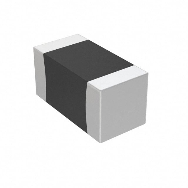
Filter (typically a capacitor) – Smooths out the ripples.
Voltage Regulator – Maintains a constant DC output.
It’s like turning a bumpy country road (AC) into a smooth highway (DC)—your electronics prefer the smooth ride.
How to Convert AC to DC: Step-by-Step Guide
Many modern devices—LEDs, microcontrollers, sensors, and chargers—run on DC voltage, while wall outlets provide AC power. To power these devices safely and reliably, converting AC to DC becomes a fundamental and necessary task.
Whether you're designing a circuit or integrating a power module into your product, understanding this process gives you control over efficiency, safety, and stability.
Here’s how the AC to DC conversion works, step by step:


Step 1: Step Down the AC Voltage
If you're starting with 220V or 110V AC, the first step is to reduce the voltage to a more manageable level—typically 12V or 24V AC. This is commonly done using a step-down transformer.
This step is important not just for voltage levels, but also for isolation—protecting low-voltage circuits and the user from the high-voltage mains.
Step 2: Rectify the AC Signal
Once the voltage is lowered, the AC signal still alternates—meaning it reverses direction multiple times per second. A bridge rectifier made of four diodes converts the AC into pulsating DC, allowing current to flow in only one direction.
Step 3: Smooth the Output
The pulsating DC isn’t stable yet. By adding a filter capacitor, typically an electrolytic capacitor (e.g., 1000µF), you can smooth out the waveform, reducing the ripple and producing a steadier DC output.
Step 4: Regulate the Voltage
Depending on your circuit’s needs, a voltage regulator (like the 7805 for 5V or LM317 for adjustable outputs) is added to ensure a constant, clean DC voltage. This prevents voltage fluctuations that could damage sensitive electronics.
Optional but important:
Heat sinks for voltage regulators to handle dissipation
Snubber or EMI filters for higher-frequency applications
Protection diodes or fuses for added safety
In summary, the process flows like this:
High-voltage AC → Step-down Transformer → Rectifier → Filter → Regulator → Clean DC Output
This method remains the foundation of both simple DIY power supplies and more complex regulated systems. Understanding it allows you to diagnose issues, customize solutions, and improve efficiency in your own designs.
Using Ac Dc Converter
An AC-DC converter is a compact, integrated module that transforms high-voltage alternating current (typically 110V or 220V AC) into a stable low-voltage direct current (such as 5V, 12V, or 24V DC). These converters are widely used in electronics, appliances, embedded systems, and IoT devices.
Unlike building a converter from discrete components, these modules offer a complete, safe, and space-saving solution. Internally, they combine rectification, filtering, and voltage regulation—often with isolation and protective circuitry.
Here are two typical examples:
HLK-PM01
This ultra-compact module takes 220V AC and outputs 5V DC at up to 600mA. It’s ideal for powering microcontrollers, sensors, or Wi-Fi modules. The HLK-PM01 is isolated, certified, and easy to embed directly on a PCB, making it perfect for low-power, embedded applications.
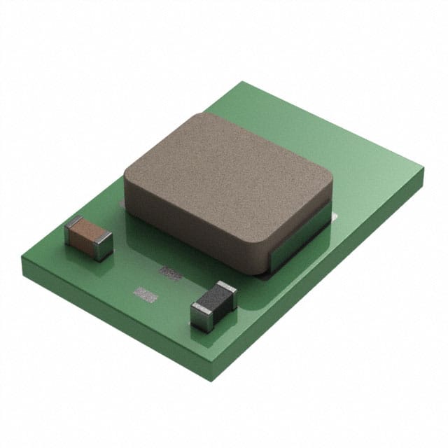
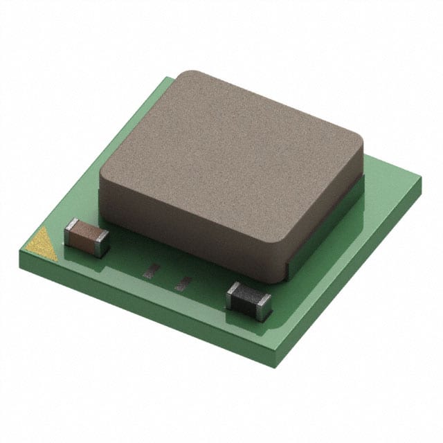
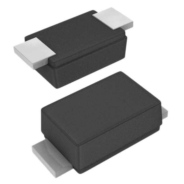
LTM4644IY#PBF
While not an AC-DC converter by itself, this high-performance DC-DC regulator module is often used downstream of an AC-DC stage. For example, an HLK module could provide 12V DC, which is then stepped down by the LTM4644 to provide four independently regulated outputs—like 5V, 3.3V, 1.8V, or 1.2V—suitable for powering FPGAs, SoCs, and other digital subsystems. It offers high efficiency, small footprint, and excellent thermal management for demanding applications.
These modules simplify the entire AC to DC conversion process—especially when your goal is reliability, space efficiency, and minimal engineering effort.
How to Convert 220V AC to 12V DC
Converting 220V AC to 12V DC can be achieved in three main ways, each with its own working principle, benefits, and trade-offs.

Transformer-Based Conversion
This method uses a step-down transformer to reduce 220V AC to 12V AC, followed by a bridge rectifier to convert it to DC. A capacitor smooths the output, and optionally a voltage regulator stabilizes it. The transformer provides electrical isolation, making this method safe and reliable. It's simple to understand and ideal for DIY use, though transformers are typically bulky and less efficient.
Switch Mode Power Supply (SMPS)
SMPS circuits convert AC to DC by first rectifying and filtering the AC input, then switching it on and off at high frequency through a control IC and transformer. This process allows for efficient voltage conversion and size reduction. SMPS modules are widely used in commercial power supplies due to their efficiency, compactness, and built-in protection. They are harder to build by hand but easy to buy as ready-made modules.
Capacitive Dropper
This method relies on a capacitor in series with the AC line to drop voltage before rectification. It eliminates the need for a transformer but offers no isolation, making it potentially hazardous. It's only suitable for very low-power, enclosed applications where no physical contact with the output occurs. Due to safety concerns and poor current capacity, it is generally not recommended for most practical uses.
DC to DC Conversion Circuit Design
Looking to design your own converter from scratch?
Key Elements:
- Bridge Rectifier: Use fast recovery or Schottky diodes for higher efficiency.
- Filter Type: Capacitive (C), LC, or π filters.
- Snubber Circuits: To suppress voltage spikes.
Advanced users should also consider thermal design, EMI compliance, and load regulation.
Best Components for AC to DC Converters
How to Reduce Ripple in AC to DC Conversion
Ripple can cause noise or malfunction in circuits.
Techniques:
- Bigger filter capacitors
- Use inductors for LC filtering
- Linear regulators after switching converters
| Method | Ripple Reduction | Cost | Difficulty |
|---|---|---|---|
| Capacitor Only | Moderate | Low | Easy |
| LC Filter | High | Medium | Medium |
| Regulator + Filter | Very High | High | Medium |
Conclusion
Converting AC to DC may sound like basic electrical work, but behind it lies a world of design decisions, safety considerations, and performance optimizations.
From choosing the right diode to exploring modular power chains with converters like LTM4644IY#PBF, this guide was built to make you feel informed, empowered, and ready to act.
Whether you’re prototyping your first device or optimizing an industrial power system, you now have the tools—and the confidence—to get it right.
Got questions, ideas, or project photos to share? Leave a comment below or connect with us. We’d love to see your builds!