A DC voltage regulator is indispensable for delivering stable power to electronic devices, safeguarding them from input fluctuations and load variations. Choosing and implementing the right regulator isn’t just about matching voltages — it requires a deep understanding of operating principles, specifications, and design trade-offs to achieve reliable, efficient, and safe performance. This article walks through key aspects you must consider, from types of regulators and critical datasheet specs to practical tips on heat dissipation and protective features.
What is a DC Voltage Regulator
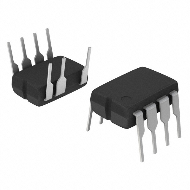
A DC voltage regulator is a device or circuit that keeps the output voltage steady even when the input voltage or load changes. It ensures reliable operation and protects sensitive electronics from damage caused by power fluctuations.
There are two main types of regulators: linear and switching. A linear regulator is simple and quiet but wastes power by turning excess voltage into heat, making its efficiency usually just 30–60%, depending on how big the voltage difference is. In contrast, a switching regulator is much more efficient—typically 85–95% or higher—because it rapidly switches on and off, storing and releasing energy without wasting much as heat.
Switching regulators also offer different topologies to match your input and output voltages: Buck, Boost and Buck-Boost. These topologies make them more versatile in a wide range of applications.
However, switching comes with trade-offs. It generates two kinds of noise: output ripple—small voltage variations caused by the switching frequency—and electromagnetic interference (EMI) from fast switching edges, which can disrupt sensitive circuits and must meet EMC standards.
Other factors also matter. For example, switching regulators generally respond faster to sudden load changes, while linear ones need a minimum voltage drop to work properly. Static current consumption affects battery standby time, and switching designs are usually more complex and costly to implement.
DC Voltage Regulator vs DC-DC Converter: What’s the Difference?
Although the terms DC voltage regulator and DC-DC converter are often used interchangeably, they aren’t exactly the same. A DC voltage regulator is a broader concept — it refers to any circuit or device that keeps the output voltage stable regardless of changes in input voltage or load current. Both linear regulators and switching regulators are types of DC voltage regulators.
On the other hand, a DC-DC converter specifically refers to a switching-based circuit that converts one DC voltage level to another using high-frequency switching and energy storage components like inductors and capacitors. All DC-DC converters are switching regulators, designed for higher efficiency and flexibility.
In short:
- DC voltage regulator = general term, includes linear and switching types.
- DC-DC converter = specific to switching technology.
Linear vs Switching DC Voltage Regulators

When choosing a DC voltage regulator, the most fundamental decision is between a linear regulator and a switching regulator, each with distinct principles, performance, and trade-offs.
A linear regulator controls output voltage by dissipating excess input voltage as heat. This simple approach keeps noise and ripple extremely low, making it ideal for sensitive analog and RF circuits. However, its efficiency is poor—typically 30–60%—because all extra power is converted into heat, and it requires the input voltage to be at least 0.7–2V higher than the output.
On the other hand, a switching regulator converts voltage by rapidly switching on and off, storing energy in inductors and capacitors before releasing it at the desired voltage. This process avoids most heat loss, delivering much higher efficiency—often 85–95% or more—even with large input-output differences.
But this efficiency and flexibility come at the cost of complexity and noise. Switching regulators generate both output ripple and electromagnetic interference (EMI), which can disturb sensitive circuits and require careful PCB layout and additional filtering to meet EMC standards.
Beyond efficiency and noise, there are other important considerations:
Quiescent (static) current: linear regulators draw very low standby current (microamps), extending battery life, while switching regulators typically consume more.
Transient response: linear regulators usually react faster to sudden load changes.
Cost and complexity: linear designs use fewer components and are easier to implement, while switching designs involve more components, careful component selection, and meticulous PCB design.
Each type shines in different applications:
Regulator TypeTypical Use Cases
- LinearSensors, ADC references, audio amplifiers, MCU analog supplies, post-regulation after a switcher
- SwitchingMain power for battery devices, LED drivers, CPU/GPU rails, motor drives, wide-input designs
DC Voltage Regulator Key Specifications

| Parameter | What It Means | Why It Matters / Design Tip |
|---|---|---|
| Output Voltage & Current | Rated output voltage and maximum load current | Must match or exceed your load requirements for stable operation |
| Dropout Voltage | Minimum input-output voltage difference needed to regulate properly | Critical in battery applications near end-of-discharge. Choose LDO for low Vin–Vout scenarios |
| Efficiency | Ratio of output power to input power, expressed as a percentage | Switchers: >85%. Linears: ≈Vout/Vin — drops sharply with high Vin. Impacts heat and battery life |
| Quiescent Current (IQ) | Regulator’s own consumption when idle | Key for battery standby life. Look for low IQ (µA level) in portable designs |
| Load Regulation | Output voltage change as load current varies | Affects voltage stability under dynamic loads — important for precision circuits |
| Line Regulation | Output voltage change as input voltage varies | Ensures stability when Vin fluctuates — e.g., from unstable adapters or batteries |
| Ripple & Noise | AC components superimposed on output — ripple (switching frequency) and wideband noise | Ripple degrades SNR in analog/RF. Check PSRR to assess suppression of input ripple |
| PSRR (Power Supply Rejection Ratio) | Ability to reject input noise from propagating to output | Crucial for sensitive analog, RF, or ADC circuits. Look for high PSRR at relevant frequencies |
| Thermal Parameters | Heat generated and dissipated by the regulator | Power dissipation = (Vin–Vout)×Iout + Vin×IQ. Ensure Tj < max by managing ΔT = Pd×θJA with cooling |
| Design Warning | — | Leave thermal margin. Check ripple/PSRR for noise-sensitive loads. Account for IQ in low-power applications |
Buck, Boost, and Buck-Boost Types

For switching regulators, topology selection depends on your input and output voltage relationship:
- Buck: steps down voltage when Vin > Vout.
- Boost: steps up voltage when Vin < Vout.
- Buck-Boost: works for Vin above or below Vout.
Each topology has unique characteristics in efficiency, complexity, and ripple. For example, in battery-powered designs where Vin drops below Vout as the battery discharges, a Buck-Boost topology ensures uninterrupted regulation.
Tip: Consider your worst-case Vin and Vout scenarios when choosing topology — and simulate performance at those extremes.
When to Add a Heat Sink
Heat can dramatically shorten a regulator’s life and compromise performance. Linear regulators in particular dissipate more power as Vin–Vout grows, but even switching regulators can overheat under high current or poor airflow.
Calculate total power dissipation and estimate temperature rise using package θJA. If the junction temperature approaches the spec limit, add a heat sink, increase copper pour area, or improve airflow.
Rule of thumb: Keep junction temperature at least 10–20°C below max rating for reliability.
Overcurrent and Thermal Protection
Built-in safety features like overcurrent protection (OCP) and thermal shutdown prevent catastrophic failures.
OCP detects excessive current, protecting both the regulator and load.
Thermal shutdown disables output if the regulator overheats, avoiding permanent damage.
Some designs also include short-circuit protection and soft-start to limit inrush currents. These features are critical for unattended or mission-critical systems.
Pro tip: Always verify the thresholds and recovery behavior of these protections to ensure they match your system’s needs.
Selection Guide for DC Voltage Regulators
| Application Scenario | Recommended Model | Type | Key Advantages |
|---|---|---|---|
| Low-noise analog circuits | TPS7A4700 | LDO | Ultra-low noise, high PSRR |
| Battery-powered portable devices | MCP1700 | LDO | Extremely low quiescent current (1.6µA) |
| General 3.3V system power supply | AMS1117-3.3 | LDO | Low cost, good stability |
| 12V/2A step-down power | MP1584EN | Buck | Compact size, high efficiency |
| Lithium battery boost (5V → 9V) | MT3608 | Boost | Simple, low cost |
| Automotive power (24V → 12V) | LM2596-ADJ | Buck | Wide input range, industrial-grade reliability |
| Solar-powered or variable input | LT8705 | Buck-Boost | Wide input voltage, high power |
Conclusion
A DC voltage regulator isn’t just a component — it’s the foundation of a stable, efficient, and reliable power supply. By understanding the principles behind linear and switching types, reading and interpreting datasheet specifications, managing heat, and leveraging safety features, you can design power systems that meet your device’s exact needs. Careful regulator selection and implementation ultimately improve performance,